Home » Blog » Calibration Procedure of the PX4 Firmware - Part I
Calibration Procedure of the PX4 Firmware - Part I
— Last modified: xiaoke das.xiaoke@gmail.com 2015/11/13 07:22
In my previous article what_is_going_on_behind_the_calibration_procedure_of_qgroundcontrol, I found out that the QGroundControl software only provides an interface of the calibration of PIXHAWK sensors. The actual calibration procedures are carried out on board. In this article, we'll continue to find out what the calibration procedures are.
Find Out the Directory of the Calibration Code in the PX4 Firmware
This time we'll turn to the source code of the PX4 firmware. First clone the git repository at https://github.com/PX4/Firmware. We need to find where the mavlink message MAV_CMD_PREFLIGHT_CALIBRATION goes in the firmware (Note this is the message sent by the startCalibration function of the QGroundControl software, as described in my previous article). I am not using an IDE this time, so in order to find the message, the following bash command was executed.
cd Firmware; for i in `find ./ -name *.[cChH]*`; do echo $i; sed -ne '/ 241/p' $i; done > abc
Note I used the number 241, instead of the name of the constant MAV_CMD_PREFLIGHT_CALIBRATION, because that name is defined in the QGroundControl source code, not in the PX4 firmware. I actually tried that name as the search keyword, but found no luck. In the generated file abc, I searched for 241 and found the following definition in ./src/modules/uORB/topics/vehicle_command.h as
#define VEHICLE_CMD_PREFLIGHT_CALIBRATION 241
and I searched the constant VEHICLE_CMD_PREFLIGHT_CALIBRATION again with the above bash command. In the file ./src/modules/commander/commander.cpp, I found the following code
	case vehicle_command_s::VEHICLE_CMD_PREFLIGHT_CALIBRATION: {

					int calib_ret = ERROR;

					/* try to go to INIT/PREFLIGHT arming state */
					if (TRANSITION_DENIED == arming_state_transition(&status, &safety, vehicle_status_s::ARMING_STATE_INIT, &armed,
							false /* fRunPreArmChecks */, mavlink_fd)) {
						answer_command(cmd, vehicle_command_s::VEHICLE_CMD_RESULT_DENIED);
						break;
					} else {
						status.calibration_enabled = true;
					}

					if ((int)(cmd.param1) == 1) {
						/* gyro calibration */
						answer_command(cmd, vehicle_command_s::VEHICLE_CMD_RESULT_ACCEPTED);
						calib_ret = do_gyro_calibration(mavlink_fd);

					} else if ((int)(cmd.param2) == 1) {
						/* magnetometer calibration */
						answer_command(cmd, vehicle_command_s::VEHICLE_CMD_RESULT_ACCEPTED);
						calib_ret = do_mag_calibration(mavlink_fd);

					} else if ((int)(cmd.param3) == 1) {
						/* zero-altitude pressure calibration */
						answer_command(cmd, vehicle_command_s::VEHICLE_CMD_RESULT_DENIED);

					} else if ((int)(cmd.param4) == 1) {
						/* RC calibration */
						answer_command(cmd, vehicle_command_s::VEHICLE_CMD_RESULT_ACCEPTED);
						/* disable RC control input completely */
						status.rc_input_blocked = true;
						calib_ret = OK;
						mavlink_log_info(mavlink_fd, "CAL: Disabling RC IN");

					} else if ((int)(cmd.param4) == 2) {
						/* RC trim calibration */
						answer_command(cmd, vehicle_command_s::VEHICLE_CMD_RESULT_ACCEPTED);
						calib_ret = do_trim_calibration(mavlink_fd);

					} else if ((int)(cmd.param5) == 1) {
						/* accelerometer calibration */
						answer_command(cmd, vehicle_command_s::VEHICLE_CMD_RESULT_ACCEPTED);
						calib_ret = do_accel_calibration(mavlink_fd);
					} else if ((int)(cmd.param5) == 2) {
						// board offset calibration
						answer_command(cmd, vehicle_command_s::VEHICLE_CMD_RESULT_ACCEPTED);
						calib_ret = do_level_calibration(mavlink_fd);
					} else if ((int)(cmd.param6) == 1) {
						/* airspeed calibration */
						answer_command(cmd, vehicle_command_s::VEHICLE_CMD_RESULT_ACCEPTED);
						calib_ret = do_airspeed_calibration(mavlink_fd);

					} else if ((int)(cmd.param7) == 1) {
						/* do esc calibration */
						answer_command(cmd, vehicle_command_s::VEHICLE_CMD_RESULT_ACCEPTED);
						calib_ret = do_esc_calibration(mavlink_fd, &armed);

					} else if ((int)(cmd.param4) == 0) {
						/* RC calibration ended - have we been in one worth confirming? */
						if (status.rc_input_blocked) {
							answer_command(cmd, vehicle_command_s::VEHICLE_CMD_RESULT_ACCEPTED);
							/* enable RC control input */
							status.rc_input_blocked = false;
							mavlink_log_info(mavlink_fd, "CAL: Re-enabling RC IN");
							calib_ret = OK;
						}
						/* this always succeeds */
						calib_ret = OK;
					}
Several functions emerged here, e.g. do_gyro_calibration(mavlink_fd), do_mag_calibration(mavlink_fd), do_accel_calibration(mavlink_fd), do_level_calibration(mavlink_fd). As the names suggest, they might contain the code for the calibration. Those functions were found in folder ./src/modules/commander/. For the accelerometer, the file accelerometer_calibration.cpp contains its calibration-related functions.
The Calibration Procedure of the Accelerometer
The following is the comment from the beginning of the file accelerometer_calibration.cpp
/**
 * @file accelerometer_calibration.cpp
 *
 * Implementation of accelerometer calibration.
 *
 */
Now, let's take a closer look at the detailed calibration procedure. By the way, calibration of the accelerometer aims to obtain a transformation from the acceleration vector measured in the sensor's coordinate system to the acceleration vector in the vehicle's body coordinate system. The sensor's bias is also calibrated. The following is from the comment of this file, which gives a fairly detailed description of this procedure.
/**
 * Transform acceleration vector to true orientation, scale and offset
 *
 * ===== Model =====
 * accel_corr = accel_T * (accel_raw - accel_offs)
 * accel_corr[3] - fully corrected acceleration vector in body frame
 * accel_T[3][3] - accelerometers transform matrix, rotation and scaling transform
 * accel_raw[3]  - raw acceleration vector
 * accel_offs[3] - acceleration offset vector
<code>
There are SIX reference positions, corresponding the the following reference vectors

<code c>/**
 * Reference vectors
 * accel_corr_ref[6][3] = [  g  0  0 ]     // nose up
 *                        | -g  0  0 |     // nose down
 *                        |  0  g  0 |     // left side down
 *                        |  0 -g  0 |     // right side down
 *                        |  0  0  g |     // on back
 *                        [  0  0 -g ]     // level
 * accel_raw_ref[6][3]
 *
 * accel_corr_ref[i] = accel_T * (accel_raw_ref[i] - accel_offs), i = 0...5
 *
 * 6 reference vectors * 3 axes = 18 equations
 * 9 (accel_T) + 3 (accel_offs) = 12 unknown constants
 *
 * Find accel_offs
 *
 * accel_offs[i] = (accel_raw_ref[i*2][i] + accel_raw_ref[i*2+1][i]) / 2
 *
 * Find accel_T
 *
 * 9 unknown constants
 * need 9 equations -> use 3 of 6 measurements -> 3 * 3 = 9 equations
 *
 * accel_corr_ref[i*2] = accel_T * (accel_raw_ref[i*2] - accel_offs), i = 0...2
 *
 * Solve separate system for each row of accel_T:
 *
 * accel_corr_ref[j*2][i] = accel_T[i] * (accel_raw_ref[j*2] - accel_offs), j = 0...2
 *
 * A * x = b
 *
 * x = [ accel_T[0][i] ]
 *     | accel_T[1][i] |
 *     [ accel_T[2][i] ]
 *
 * b = [ accel_corr_ref[0][i] ]	// One measurement per side is enough
 *     | accel_corr_ref[2][i] |
 *     [ accel_corr_ref[4][i] ]
 *
 * a[i][j] = accel_raw_ref[i][j] - accel_offs[j], i = 0;2;4, j = 0...2
 *
 * Matrix A is common for all three systems:
 * A = [ a[0][0]  a[0][1]  a[0][2] ]
 *     | a[2][0]  a[2][1]  a[2][2] |
 *     [ a[4][0]  a[4][1]  a[4][2] ]
 *
 * x = A^-1 * b
 *
 * accel_T = A^-1 * g
 * g = 9.80665
The calibration procedure above is clearly a standard textbook one. The following is a description of the procedure in mathematical equations.
apart from the final Rotation part. Since the calibration procedure will itself obtain a rotation matrix to account for the misalignment of the sensor's axes and the vehicle's body axes, so why there is another rotation procedure stated here? We'll solve this problem first.
The Rotation Myth
I searched the keyword “rotate” in the main calibration function do_accel_calibration() and found the following two lines
	/* measurements completed successfully, rotate calibration values */
	param_t board_rotation_h = param_find("SENS_BOARD_ROT");
A constant SENS_BOARD_ROT comes out, what is this? It turned out to be a constant defined in ./src/modules/sensors/sensor_params.c as
PARAM_DEFINE_INT32(SENS_BOARD_ROT, 0);
Apparently it does not refer to the misalignment of the sensor's coordinate system and the vehicle's since the misalignment is the result of the calibration. Anyone who has done the calibration procedure in QGroundControl will remember there is a drop-down listbox asking the user to choose the orientation of the vehicle, as in Fig. 2.
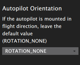 Figure 2. The dropdown listbox which asks for the orientation of the vehicle in the sensors config panel of QGroundControl.
So could this drop-down listbox relate to the SENS_BOARD_ROT constant? We'll have to go back to the QGroundControl's code to check. The string in the box “ROTATION_NONE” could be a clue.
It is a property defined in src/AutoPilotPlugins/PX4/SensorsComponent.qml as
  readonly property var rotations: [
        "ROTATION_NONE",
        "ROTATION_YAW_45",
        "ROTATION_YAW_90",
        "ROTATION_YAW_135",
        "ROTATION_YAW_180",
        "ROTATION_YAW_225",
        "ROTATION_YAW_270",
        "ROTATION_YAW_315",
        "ROTATION_ROLL_180",
        "ROTATION_ROLL_180_YAW_45",
        "ROTATION_ROLL_180_YAW_90",
        "ROTATION_ROLL_180_YAW_135",
        "ROTATION_PITCH_180",
        "ROTATION_ROLL_180_YAW_225",
        "ROTATION_ROLL_180_YAW_270",
        "ROTATION_ROLL_180_YAW_315",
        "ROTATION_ROLL_90",
        "ROTATION_ROLL_90_YAW_45",
        "ROTATION_ROLL_90_YAW_90",
        "ROTATION_ROLL_90_YAW_135",
        "ROTATION_ROLL_270",
        "ROTATION_ROLL_270_YAW_45",
        "ROTATION_ROLL_270_YAW_90",
        "ROTATION_ROLL_270_YAW_135",
        "ROTATION_PITCH_90",
        "ROTATION_PITCH_270",
        "ROTATION_ROLL_270_YAW_270",
        "ROTATION_ROLL_180_PITCH_270",
        "ROTATION_PITCH_90_YAW_180"
    ]
and the next line
property Fact sens_board_rot: controller.getParameterFact(-1, "SENS_BOARD_ROT")
seems to get this parameter from somewhere. We know that PIXHAWK stored a bunch of variables in the flash memory or EEPROM. Could the above line be getting the values from the flash memory? I found the following parameters stored in the flash memory of PIXHAWK
1	50	SENS_BOARD_ROT	0	6
1	50	SENS_BOARD_X_OFF	                        0	9
1	50	SENS_BOARD_Y_OFF	                        0	9
1	50	SENS_BOARD_Z_OFF	                        0	9
which was also listed in the QGroundControl PARAMETERS panel as in Fig. 3.
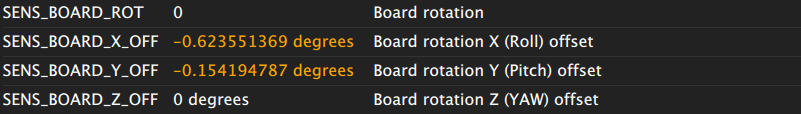 Figure 3. The sensor's parameters panel of QGroundControl.
The definition of these parameters were found in file src/AutoPilotPlugins/PX4/ParameterFactMetaData.xml as
<parameter default="0" name="SENS_BOARD_ROT" type="INT32">
      <short_desc>Board rotation</short_desc>
      <long_desc>This parameter defines the rotation of the FMU board relative to the platform. Possible values are: 0 = No rotation 1 = Yaw 45° 2 = Yaw 90° 3 = Yaw 135° 4 = Yaw 180° 5 = Yaw 225° 6 = Yaw 270° 7 = Yaw 315° 8 = Roll 180° 9 = Roll 180°, Yaw 45° 10 = Roll 180°, Yaw 90° 11 = Roll 180°, Yaw 135° 12 = Pitch 180° 13 = Roll 180°, Yaw 225° 14 = Roll 180°, Yaw 270° 15 = Roll 180°, Yaw 315° 16 = Roll 90° 17 = Roll 90°, Yaw 45° 18 = Roll 90°, Yaw 90° 19 = Roll 90°, Yaw 135° 20 = Roll 270° 21 = Roll 270°, Yaw 45° 22 = Roll 270°, Yaw 90° 23 = Roll 270°, Yaw 135° 24 = Pitch 90° 25 = Pitch 270°</long_desc>
    </parameter>
    <parameter default="0.0" name="SENS_BOARD_Y_OFF" type="FLOAT">
      <short_desc>Board rotation Y (Pitch) offset</short_desc>
      <long_desc>This parameter defines a rotational offset in degrees around the Y (Pitch) axis. It allows the user to fine tune the board offset in the event of misalignment.</long_desc>
      <unit>degrees</unit>
    </parameter>
    <parameter default="0.0" name="SENS_BOARD_X_OFF" type="FLOAT">
      <short_desc>Board rotation X (Roll) offset</short_desc>
      <long_desc>This parameter defines a rotational offset in degrees around the X (Roll) axis It allows the user to fine tune the board offset in the event of misalignment.</long_desc>
      <unit>degrees</unit>
    </parameter>
    <parameter default="0.0" name="SENS_BOARD_Z_OFF" type="FLOAT">
      <short_desc>Board rotation Z (YAW) offset</short_desc>
      <long_desc>This parameter defines a rotational offset in degrees around the Z (Yaw) axis. It allows the user to fine tune the board offset in the event of misalignment.</long_desc>
      <unit>degrees</unit>
    </parameter>
It can be seen that there is a direct correspondence between the definition of SENS_BOARD_ROT and the rotations property, so we can confidently say that the SENS_BOARD_ROT variable in the PX4 program corresponds to this bit of the settings in QGroundControl.
Note: src/AutoPilotPlugins/PX4/ParameterFactMetaData.xml file is a pretty good one, since it gives a clear description to all the variables stored in the flash memory.
Now, we come back to the PX4 code, two problems remain: first, how the calibration is actually done; second, how are the calibration results stored?
The Calibration Code
Let's take a closer look at the Rotation section of the comment.
 * ===== Rotation =====
 *
 * Calibrating using model:
 * accel_corr = accel_T_r * (rot * accel_raw - accel_offs_r)
 *
 * Actual correction:
 * accel_corr = rot * accel_T * (accel_raw - accel_offs)
 *
 * Known: accel_T_r, accel_offs_r, rot
 * Unknown: accel_T, accel_offs
 *
 * Solution:
 * accel_T_r * (rot * accel_raw - accel_offs_r) = rot * accel_T * (accel_raw - accel_offs)
 * rot^-1 * accel_T_r * (rot * accel_raw - accel_offs_r) = accel_T * (accel_raw - accel_offs)
 * rot^-1 * accel_T_r * rot * accel_raw - rot^-1 * accel_T_r * accel_offs_r = accel_T * accel_raw - accel_T * accel_offs)
 * => accel_T = rot^-1 * accel_T_r * rot
 * => accel_offs = rot^-1 * accel_offs_r
Basically, what the comments say is that the sensor model is assumed to be linear, as in the two models above. The two models are equivalent. The rotational matrix rot is known from the predetermined SENS_BOARD_ROT variable, and the remaining unknowns are accel_T and accel_offs, which are exactly the same as the ones in the unrotated calibration version. it accounts for the rotations defined in the constant “SENS_BOARD_ROT”. Now, let's have a look at the code implementation of the algorithm. The calibration is carried out in this function
calibrate_return cal_return = do_accel_calibration_measurements(mavlink_fd, accel_offs, accel_T, &active_sensors);
In function do_accel_calibration_measurements,
A function named calibrate_from_orientation() is called by the following command
result = calibrate_from_orientation(mavlink_fd, cancel_sub, data_collected, accel_calibration_worker, &worker_data, false /* normal still */);
which I guess carries out the data collection task and the task of calculating the averages of the data, which is done by function accel_calibration_worker(), this function is passed as a handle to the previous function.
In the last part of this function, the core calibration algorithm is done through the following function
calibrate_return calculate_calibration_values(unsigned sensor, float (&accel_ref)[max_accel_sens][detect_orientation_side_count][3], float (&accel_T)[max_accel_sens][3][3], float (&accel_offs)[max_accel_sens][3], float g)
In the algorithm, the rotation is done after the calibration is done. The following code implements the rotation
	/* measurements completed successfully, rotate calibration values */
	param_t board_rotation_h = param_find("SENS_BOARD_ROT");
	int32_t board_rotation_int;
	param_get(board_rotation_h, &(board_rotation_int));
	enum Rotation board_rotation_id = (enum Rotation)board_rotation_int;
	math::Matrix<3, 3> board_rotation;
	get_rot_matrix(board_rotation_id, &board_rotation);
	math::Matrix<3, 3> board_rotation_t = board_rotation.transposed();
function param_get() stores an integer corresponding to the rotation configuration into board_rotation_int, then the corresponding matrix is obtained by function get_rot_matrix() and stored in board_rotation, which is a matrix object. The rotated offset vector and misalignment matrix are computed by the following operations.
		/* handle individual sensors, one by one */
		math::Vector<3> accel_offs_vec(accel_offs[i]);
		math::Vector<3> accel_offs_rotated = board_rotation_t * accel_offs_vec;
		math::Matrix<3, 3> accel_T_mat(accel_T[i]);
		math::Matrix<3, 3> accel_T_rotated = board_rotation_t * accel_T_mat * board_rotation;
Note that not all the parameters in the misalignment matrix is stored into the flash memory. The following are the code saving the calibration results.
		accel_scale.x_offset = accel_offs_rotated(0);
		accel_scale.x_scale = accel_T_rotated(0, 0);
		accel_scale.y_offset = accel_offs_rotated(1);
		accel_scale.y_scale = accel_T_rotated(1, 1);
		accel_scale.z_offset = accel_offs_rotated(2);
		accel_scale.z_scale = accel_T_rotated(2, 2);

		bool failed = false;

		/* set parameters */
		(void)sprintf(str, "CAL_ACC%u_XOFF", i);
		failed |= (OK != param_set_no_notification(param_find(str), &(accel_scale.x_offset)));
		(void)sprintf(str, "CAL_ACC%u_YOFF", i);
		failed |= (OK != param_set_no_notification(param_find(str), &(accel_scale.y_offset)));
		(void)sprintf(str, "CAL_ACC%u_ZOFF", i);
		failed |= (OK != param_set_no_notification(param_find(str), &(accel_scale.z_offset)));
		(void)sprintf(str, "CAL_ACC%u_XSCALE", i);
		failed |= (OK != param_set_no_notification(param_find(str), &(accel_scale.x_scale)));
		(void)sprintf(str, "CAL_ACC%u_YSCALE", i);
		failed |= (OK != param_set_no_notification(param_find(str), &(accel_scale.y_scale)));
		(void)sprintf(str, "CAL_ACC%u_ZSCALE", i);
		failed |= (OK != param_set_no_notification(param_find(str), &(accel_scale.z_scale)));
		(void)sprintf(str, "CAL_ACC%u_ID", i);
		failed |= (OK != param_set_no_notification(param_find(str), &(device_id[i])));
It can be seen that only the diagonal elements of the misalignment matrix is stored and the offsets are stored as well.
Note two functions
int do_accel_calibration(int mavlink_fd);
int do_level_calibration(int mavlink_fd);
are the top level function of this calibration procedure. The second implements the level calibration. I'll discuss this later.
Still another myth remains, why only the diagonal elements of the calibration matrix is stored?